

How To Always Point Blender Camera At An Object
3D View ![]() windows are used to visualize 3D scenes. Y'all'll do a lot of work in these windows, then you will need to learn your way around.
windows are used to visualize 3D scenes. Y'all'll do a lot of work in these windows, then you will need to learn your way around.
| | The 3D view but shows an approximation of the terminal appearance of the scene. The overall geometry should be correct, but don't await accurate rendition of materials, textures, lighting etc, since that can exist very time consuming. The 3D view is designed to respond to your deportment at interactive speeds. At that place are additional view options (wireframe, hiding etc) that make it easier to see which parts of the model you lot're working on, have no effect on the final return. You tin change your viewpoint at any time (which will exist essential while working on your model/scene), while the viewpoint of the render is controlled past the camera position. |
In this module, you'll acquire:
- to recognize 10 things commonly seen in viewports
- to tell which style Blender is in
- how to change viewport options and viewpoints
- how to position the 3D cursor
You'll also learn the fundamentals of:
- visibility layers
The Viewport and its Contents [edit | edit source]
Aside from its header, the residual of a 3D View window is its viewport. Y'all use viewports any time you need an up-to-engagement view of the scene you lot're working on.
Viewports are busy places. Continue a scavenger hunt and run across what you can find in a unproblematic viewport.
- Launch Blender.
- Just so we're all looking at the aforementioned scene, load the factory settings using File → Load Mill Settings.
- Ostend the "Load Factory Settings" popup with LMB (or Enter).
- If the NumLock indicator on your keyboard is unlit, press NumLock then that numpad hotkeys will piece of work properly.
(If yous're unsure what LMB means, please review the Keystroke, Button, and Carte Notation module.)
Y'all should encounter something like this:

Here the viewport has been outlined in red to focus your attention on it.
A Virtual Scavenger Hunt [edit | edit source]
Await at the default scene and observe the following eight items:
- In the Center
i.  a solid grayness cube with orange edges.
-
- This is the default cube, your first Blender object!
2.  Three arrows, one red, one green and one blue, their tails joined to a white circle
-
- This is not an object (part of your model/scene), only role of Blender's user interface for manipulating objects. Information technology is the manipulator, also known equally the 3D transform widget.
- The arrows represent the directions of the X, Y and Z axes of the currently chosen transform orientation coordinate system. Initially this is the global coordinate system.
- The circle represents the eye of the selected object (the cube).
- If you lot don't know what the "global coordinate system" is, delight review the module on Coordinate Spaces in Blender.
If you lot don't run into the manipulator...
- It's possible that a tool is active. Press Esc to cancel whatever tool activity.
- Another possibility is that the manipulator has been disabled:
- Toggle it on or off with Ctrl+ Infinite.
iii. ![]() A ruddy-and-white striped circle with black cross-hairs
A ruddy-and-white striped circle with black cross-hairs
-
- This is not an object. It is the 3D Cursor, which indicates where newly-created objects will appear in the scene.
- The cursor is similar to the insertion point in a text editor, which indicates where new text will exist inserted in a document.
- In the Lower Left Corner
4. 
-
- This is non an object. Information technology is the mini centrality, and its orientation matches that of the global coordinate system, with the usual conventions: red for X, greenish for Y and blueish for Z. Recall of it as a little compass, reminding you which style is left/right, forepart/back and up/down.
five. The notation "(ane) Cube"
- This is not an object. It is object info, indicating that:
- You're viewing the get-go frame of an animation.
- and
- The current or most recently selected object is named "Cube".
- In the Upper Left Corner
6. The notation "User Persp"
- This is not an object. This tells you which mode the viewport is in. The get-go discussion volition modify if you select one of the perfect views or the camera view (see below), otherwise it just says "User", and the second discussion is "Persp" or "Ortho" to signal whether this is a perspective or orthographic view.
- To the Right of Center
7. ![]() A black round thing that resembles a sun symbol
A black round thing that resembles a sun symbol
-
- This represents a lamp, a light source for the scene. (Information technology is an object.)
8. ![]() A pyramidal wireframe item
A pyramidal wireframe item
-
- This represents a photographic camera, a viewpoint that tin can be used for rendering. (Information technology besides, is an object.) The camera is looking at the base of operations of the pyramid. The solid triangle fastened to one side of the base is to remind you which style is up in the paradigm that the camera takes.
- On a small display, the camera might initially lie outside of the viewport and thus be invisible. In that instance, Scroll to zoom out until it becomes visible.
- Throughout
9. A dark greyness groundwork, divided into squares by lighter lines. This is the grid floor, which you can (but don't have to) use as a ground aeroplane for positioning your models.
-
- Each filigree square is ane blender unit of measurement (or BU) on a side. A BU can be whatever you lot wish, eastward.thousand. an inch, a centimeter, a mile, or a cubit. Blender lets you cull your scene scale in the Scene tab of the Properties Panel.
10. 3 mutually perpendicular coloured lines associated with the grid floor: the cerise and green ones lying horizontally in the floor and the blue one running vertically. These are the global coordinate axes for orienting your scene. Ruddy is the X-centrality, green the Y-centrality, and bluish the Z-centrality.
- In Blender 2.67a, yous tin can't see the bluish line for Z-axis hither, only you can meet it in Front or Side view.
Modes [edit | edit source]
Blender has many modes, i.e. settings that affect its behavior, and this is peculiarly true of the 3D View window.
Sometimes it's not obvious which fashion is active. This leads to manner errors where Blender volition exercise something you didn't look considering you thought it was in i manner and it was really in another.
The function performed by a hotkey or mouse button can depend on:
- what manner the user interface is in,
- whether the keyboard is in NumLock mode,
- which window is active,
- the way the active window is in,
- which item or items are selected,
- whether you've initiated a hotkey sequence.
It helps to recognize the common modes and how to get out of them.
Object Mode vs. Edit Mode [edit | edit source]
The 3D View windows are commonly in Object Mode. In this fashion:
-
- The mouse pointer is the default pointer normally used on other programs.
- RMB is used to select objects in the scene.
- In versions 2.8 and above Utilize LMB to select objects in the scene
If in that location are objects in the scene, you can become into five other modes:
- Edit Mode: used to edit the shapes of objects
- The mouse pointer is a thin changed-video cross.
- RMB is used to select vertices, faces or edges of the current object.
- Printing Tab to enter/exit this style.
- Sculpt Mode/Vertex Paint/Texture Pigment/Weight Pigment
- The mouse pointer is now a thin, orangish (white in Texture Paint) circle.
These modes are also indicated past a card in the 3D View header. You can utilise this menu to change modes.
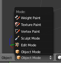
These modes are a setting shared by all 3D View windows. In other words, when yous change the mode in one window, whatever other 3D View windows change manner also.
Viewport Options [edit | edit source]
| | The options in this section merely affect 3D View viewports. They practise non affect renders. |
Solid vs. Wireframe [edit | edit source]
Past default, the 3D View window draws objects using the Solid drawtype, in which surfaces are opaque. To toggle between Solid and Wireframe drawtype (edges but, no faces) for a item viewport:
- Activate the 3D View window
- Press Z.
Alternatively, you lot can choose these and other drawtypes from the "Viewport shading" menu in the 3D View window header.
Orthographic vs. Perspective [edit | edit source]
By default, viewports draw orthographic views. To toggle a viewport betwixt orthographic and perspective views:
- Activate the 3D View window.
- Press Num5.
(If you're unsure what the difference is, please review the "Orthographic Views" module and the "Perspective Views" module.)
Note this perspective versus orthographic setting for the 3D viewport is completely separate from the similar setting in the photographic camera properties. The former takes effect while yous're working on the model, the latter when you return.
So why have a divide setting for the 3D view? Considering certain aspects of modelling are easier in one view than another. If the final render will be using perspective, then showing perspective in the 3D view naturally gives you a improve idea of how the terminal render will look. Only perspective foreshortening can sometimes brand it hard to ensure the model has the proper shape, which is why there is the option to switch to orthographic view.
If yous accept trouble distinguishing betwixt orthographic view and perspective view
... yous should activate the View Name option. This is enabled by default and causes the name of the current view ("User Persp", for instance) to announced in the upper left corner of every viewport. If in that location is no text, then y'all tin can enable it by:
- Accessing the User Preferences window.
- Click on the Interface tab.
- Enable View Proper name.
Changing Your Viewpoint, Part One [edit | edit source]
Each viewport has a viewpoint, which takes into account:
- the location of the viewer in the 3D scene (In that location doesn't need to be an object at that location.)
- the direction the viewer is looking
- the magnification (or zoom gene) used
Changing your viewpoint allows you to navigate your manner through a 3D scene.
We'll start with iii very bones techniques:
- Zooming
- Orbiting/View Rotation
- Perfect Views.
Additional techniques will be covered later in this module.
Zooming [edit | edit source]
Blender offers several ways to zoom in and out:
- Use Gyre
- Click and drag vertically with Ctrl+ MMB.
- Use Num+ and NUM− to zoom in and out in small increments.
Notation the following limitations of Blender'southward zoom feature:
- If the viewport is in orthographic mode, Blender zooms as if looking through a telescope. Y'all can increase the magnification, just the viewpoint's location doesn't change. For this reason, y'all cannot zoom into or through objects in orthographic mode.
- If the viewport is in perspective mode, Blender zooms to the eye of the viewport. The viewpoint tin pass through objects, but can't pass beyond this signal, no affair what you lot do. Zooming simply gets slower and slower and slower. If the center of the viewport is somewhere you don't wait, zooming may appear to exist cleaved.
Orbiting and View Rotation [edit | edit source]
Let's fly around the default cube, viewing it from different angles. In this manner you'll encounter that information technology really is a cube, centered on the origin, half above the X-Y plane and half below it.
- Activate the 3D View window by placing the mouse arrow within it.
- Now you can:
- Click and drag with MMB to orbit freely around the center of the view.
- Use Shift+ Alt+ SCROLL to rotate the viewpoint vertically around the center of the view.
- Use Num2 and Num8 to rotate the viewpoint vertically around the eye of the view in 15-caste increments.
- Use Ctrl+ Alt+ SCROLL to rotate the viewpoint around the Z centrality.
- Use Num4 and Num6 to rotate the viewpoint effectually the Z axis in 15-degree increments.
If this is all very confusing for you, don't worry! You'll acquire equally you get more experience.
When y'all are finished flying around the cube, you can restore the original view by reloading the factory settings with File → Load Manufacturing plant Settings.
If the hotkeys don't work...
You lot may have pressed number keys above the letters instead of the ones on the numpad. If y'all practice, the default cube volition vanish. This is considering the scene consists of multiple layers. The default cube is in layer 1, and you've told Blender to switch to the layer of the number you just pressed. The selected object (the cube in this case) remains in layer 1, which is no longer visible. For case, 2Key tells Blender to switch to layer ii. To switch to layer 1 again, press 1Key. Y'all tin view the different layers by clicking on the niggling squares on the layer map: ![]()
User comments
The Shift + Alt + Scroll and Ctrl + Alt + Curl practise non work for me with factory settings in Blender two.92.0
| | The middle of the viewport is not marked, i.e. information technology's hard to tell where it is. This can crusade unexpected beliefs during rotation. |
Perfect Views [edit | edit source]
Information technology'due south often useful to go a perfect view of a scene, i.due east. to view it along one of the chief axes, with the other 2 primary axes oriented up-downward and left-right.
| Hotkey | View | Axis Pointing Right | Centrality Pointing Up |
|---|---|---|---|
| Num7 | "summit" | +10 | +Y |
| Ctrl+ Num7 | "bottom" | +Ten | -Y |
| Num1 | "forepart" | +Ten | +Z |
| Ctrl+ Num1 | "rear" | -X | +Z |
| Num3 | "right side" | +Y | +Z |
| Ctrl+ Num3 | "left side" | -Y | +Z |
The following screenshot shows all three perfect views plus camera perspective for the Suzanne primitive:

This layout is used so often, information technology has a keyboard shortcut: ( CTRL+ ALT+ Q).
Positioning the 3D Cursor [edit | edit source]
Positioning the 3D cursor is a very basic operation, yet one that many beginners find challenging. It touches on an outcome common to all 3D graphics software: "How do you specify points in a 3D scene when we can only come across two dimensions at a time?"
Basic Technique [edit | edit source]
- Get into either Object Style or Edit Mode.
- Motility the mouse pointer to the desired position (in any viewport).
- Click LMB.
Ii Challenges [edit | edit source]
Challenge #1. Using but tools presented thus far, attempt positioning the 3D cursor on the virtual camera.
Try it!
When you're washed, check your work by orbiting the photographic camera.
Possibly you thought y'all were done when you clicked on the camera. Merely the moment you inverse your viewpoint, you probably found that the 3D cursor was really behind (or in front of) the camera.
Hints:
- Try positioning the cursor in two unlike perfect views.
- Utilise orthographic, not perspective, view.
Challenge #2. Using only tools presented thus far, effort repositioning the 3D cursor at the origin (that is, at the eye of the cube).
As before, check your work by orbiting the cube. Don't spend too much time on this.
User Comments
"I found that I would select the cube when left clicking on it in object mode, if the "Use 3d transform manipulator" push button was enabled. To toggle this off, you click on the grey pointing hand in the 3d panel header, or (Ctrl Space)."
"When y'all want the cursor back into the cube, just select the camera with RMB, put the cursor into the cube post-obit the steps above, and re-select the cube with RMB."
"I've discovered information technology helps a lot if y'all are in Object Fashion and not in Edit Mode. I wrote the following earlier discovering this: The problem with this practise, for me, is that left clicking on the cube selects the cube instead of moving the 3d cursor. If I click on the cube exterior of its central white circumvolve I can get the cursor to move at that place, but only to outside of this white circumvolve, and even then this only works sometimes."
"I failed at this until I had zoomed in close enough to the cube. When I was too far zoomed out I kept selecting the cube rather than creating an edit point."
"I had the same trouble and found it was because the cube was selected. I made sure I was in object mode, right clicked on the camera to select the camera instead of the cube, and I could then position the edit point in the cube. Notwithstanding, doing this messed upward the next office of the tutorial because you cannot switch into edit mode with the camera selected! Perchance the proposition of trying to put the 3D cursor in the cube should exist dropped as it raises too many questions at this phase."
"You tin can deselect all by pressing the AKEY or the select button in the 3D View."
"Use wireframe fashion works improve to get the cursor in."
"To become it dorsum in the cube: 1) Brand certain yous're in object mode. two) Select the cube. 3) Object > Snap > Cursor to selection (cursor refers to the 3D cursor hither) and then it puts information technology right in the center of the cube."
"I think information technology'south an essential indicate to note that in club to place the cursor inside the cube, the cube must Non be selected. AKEY was probably the best way to deselect the object."
"If I think correctly, undo history gets cleared when you switch between object and edit mode."
"I wasted a lot of time here. Give thanks you to the reader who suggested (on the 3D view header) Object > Snap > Cursor to pick. It was the only thing that worked to get the cursor visible again and placed where clicked."
"I missed the point of the practice showtime time around. You can't fix a 3D bespeak on a 2D screen without technique. Orthographic views are crucial. I am just learning, but take that, at least, away from information technology."
"Positioning the 3D cursor in othographic views always made it snap to the cube surface, making it incommunicable to centre precisely. Set this past disabling "Cursor Depth" on the "interface" tab nether "User Preferences".
"The phrase cheque your piece of work by orbiting the camera needs boosted clarification, such equally a referenced section or the precise commands to use."
More Ways to Position the Cursor [edit | edit source]

Here'due south an piece of cake way to position the cursor at the centre of an object:
- Brand sure Blender is in Object Mode, with the object selected.
- Move the mouse arrow to whatever 3D View window.
- Snap the cursor to the selected object using either:
- Shift+ S → Cursor to Selected
- or
- Object → Snap → Cursor to Selected
Here'due south two easy ways to relocate the cursor to the scene'due south origin (0, 0, 0):
- Move the mouse pointer to whatsoever 3D View window.
- Printing Shift+ C to reset the cursor to the origin.
- Note that this too changes the view location, meaning that when you zoom in, you won't zoom in to the scene origin.
- A ameliorate mode is to click Object → Snap → Cursor to Center
- You lot can also do this past Shift+ South → Cursor to Center.
Changing Your Viewpoint, Part Two [edit | edit source]
At present you'll acquire some additional techniques for obtaining the view you desire:
- Panning
- Centering
- Jumping to the camera's viewpoint
- Zooming in on a selected area
Panning [edit | edit source]
When you orbited the cube, the viewpoint'south position and direction both changed at the same time. You besides can shift the viewpoint up-down or left-correct without changing its direction. (This is similar to the side-scrolling effect in the classic Mario and Sonic video games.)
This is called panning, and it's an important skill to chief. Try information technology at present:
- Actuate a 3D View window by placing the mouse pointer within information technology.
- Now you lot tin:
- Use Shift+ Curlicue to pan up and down.
- Apply Ctrl+ Num2 and Ctrl+ Num8 to pan up and downwardly in small increments.
- Use Ctrl+ Whorl to pan left and right.
- Use Ctrl+ Num4 and Ctrl+ Num6 to pan left and correct in small-scale increments.
- Click and drag with Shift+ MMB or Shift+ Alt+ LMB to pan freely in the viewplane.
Yous will likely discover this to be a distraction in some cases. To movement the viewpoint position back to the centre, snap the cursor to the centre, and then click View → Align View → Centre View to Cursor. You could too snap the cursor to the heart then press Ctrl+ Num..
In versions ≥2.74 you can besides use Alt+ Dwelling house to heart the view to the cursor.
Centering [edit | edit source]
When you zoom or rotate the view, you always zoom or rotate around the centre of the view.
To brand sure everything in your scene is visible:
- Press Home.
To center the view on an arbitrary betoken:
- Motion the 3D cursor to the point of interest.
- Verify the cursor position from a second viewpoint.
- Printing Alt+ Domicile to middle the view.
To centre the view on an object in the scene:
- Make sure Blender is in Object Way.
- Zoom out until the object is in the viewport.
- If whatever objects are selected, use A (or Select → Select/Deselect All) to deselect them.
- Select the object of interest by clicking RMB on it.
- Press Num. to heart the view.
Jumping to the Camera'south Viewpoint [edit | edit source]
To come across the scene as the virtual photographic camera sees it, press Num0. Later, you can rotate, pan, and zoom normally, only the virtual photographic camera will not follow. To go back to your previous view, press Num0 again. (In the latest versions of Blender, the virtual camera can be made to follow all the changes fabricated in viewpoint while in camera view by checking the option "Lock Camera to View" on the Transform console. Hit North on your keyboard to bring upwards the transform panel. To disable this option uncheck "Lock Photographic camera to View.")
Zooming into a Selected Area [edit | edit source]
Suppose you want to get an farthermost closeup of a particular area. Because in that location'due south no center mark on the viewport, you might have to pan and zoom several times to get the desired view.
The shortcut for zooming to an area is:
- Activate a 3D view window that contains the surface area of involvement.
- Press Shift+ B. A crosshair appears in the viewport.
- Click and drag with LMB to draw a rectangle around the area of interest.
- When you release LMB, the viewport will zoom in on the area you selected.
[edit | edit source]
Yous tin likewise change your viewpoint in the 3D view by "walking" or "flying" through it. To activate this, printing SHIFT+ F. Past default in Blender ii.70, this puts you in "walk" mode. Before versions merely offered "fly" mode. (In Blender two.70 and after, you can choose which i you prefer in User Preferences, under the Input tab.)
In both modes, helpful prompts appear in the header of the 3D view window to remind yous of the key functions while the mode is in effect. When you have reached the position and orientation you want, press LMB or ENTER or Infinite to terminate the navigation style and stay there, or RMB or ESC to abandon the navigation mode and exist teleported immediately back to your original position and orientation. (In 2.77+, pressing SPACE will teleport yous to where the cross hairs bespeak towards.)
Walk Mode [edit | edit source]
In this mode, you motility the mouse to turn your view upwardly/downward/left/correct, and W, A, S and D or the corresponding arrow keys to motility frontward, left, back or right, and E and Q to move upward or down respectively. Hold a movement central down to keep moving. Movement stops as soon as y'all release information technology. Pressing MMB will "teleport" you close to whatever objects lie inside the crosshairs at the heart of the view.
You tin also apply TAB to turn on gravity. Make sure at that place is a floor or other object nether you to land on! With gravity on, you tin no longer apply the vertical movement keys, simply yous tin can use V to make jumps. Printing TAB again to turn gravity off.
Fly Mode [edit | edit source]
In this older mode, moving the mouse to change the view works the same as in Walk mode, but the above direction keys ( W, A, S, D, E, Q and the arrows) apply "thrust" in the respective directions, so you keep moving after releasing the primal. Press the central repeatedly to increase your speed in that direction, or printing the key for the contrary thrust direction to reduce your speed. Y'all can coil the mouse cycle up to apply forwards thrust, or curlicue it down to apply backward thrust.
Your current velocity vector automatically changes direction with you when you turn. Thus, you tin can apply a unmarried burst of sideways thrust while facing an object, then, without applying any additional thrust, go along turning to face up the object, and you volition get right effectually it.
Visibility Layers [edit | edit source]
Every object in the scene is assigned to one or more than of 20 visibility layers.
Visibility layers accept many uses:
- You lot can put scenery, characters, particles, and lamps in different layers, to help organize your scene.
- Past irresolute which layers are visible, yous can simplify your view of the scene and piece of work with simply i or two layers at a time.
- When rendering, only visible layers are included. You tin apply this to render your scene layer by layer, checking each layer separately.
- You tin configure lamps to illuminate just objects in the aforementioned layer.
![]()
Left: Viewing layer ane just.
Correct: Viewing all 20 layers.
In Object Mode, you can tell which layers are visible by looking at the xx small boxes located in the 3D View header between the Transform Orientation carte and the "Lock" button. The acme row of boxes represents layers i through x, with 1 being the leftmost and 10 being the rightmost. Similarly, the bottom row of boxes represents layers xi through twenty.
Hotkeys [edit | edit source]
- To view just one of layers 1 - ix, press 1KEY .. 9KEY.
- To view just layer 10, press 0Key.
- To view just one of layers 11 - 19, press ALT+ 1KEY .. ALT+ 9KEY
- To view merely layer 20, press ALT+ 0KEY.
- To toggle the visibility of 1 of layers 1 - ix without affecting the visibility of the other layers, press SHIFT+ 1KEY .. SHIFT+ 9KEY.
- To toggle the visibility of layer x without affecting the visibility of the other layers, press SHIFT+ 0KEY.
- To toggle the visibility of 1 of layers 11 .. nineteen without affecting the visibility of the other layers, press ALT+ SHIFT+ 1KEY .. ALT+ SHIFT+ 9KEY.
- To toggle the visibility of layer 20 without affecting the visibility of the other layers, press ALT+ SHIFT+ 0KEY.
- To make all layers visible at in one case, press ~. Press ~ once again to return to your previous layer visibility setting.
Note to AZERTY users:
On the AZERTY keyboard layout, the standard number keys are the &é"'(-è_çà keys. Do non use Shift unless you want to toggle visibility as explained below.
Property downwardly Shift while selecting a layer (by keyboard or mouse) will, instead of making simply that layer visible, toggle the visibility. In this mode, you lot tin can select combinations or to hide particular layers.
The cardinal to press to select all layers at once differs past keyboard layout. It is:
- ¬' (the key under Esc) on UK keyboards,
- `~ United states of america,
- ö German, Swedish, Finnish and Hungarian,
- ¨ Swiss German language,
- æ Danish,
- ù AZERTY,
- ø Norwegian,
- Ñ Spanish,
- ç Portuguese,
- " Brazilian Portuguese,
- ò Italian, and
- ё Russian.
Later on pressing the same cardinal, property down Shift while pressing it again will restore the visibility settings you had before you made all layers visible.
When but ane layer is selected, new objects are automatically assigned to that layer. When two or more than layers are visible, new objects are assigned to the nigh recently visible layer.
Count Your Polys [edit | edit source]
If you lot desire to count the polygons in your scene, the data is bachelor in the Info Header.

As you can come across in the above image, this scene has 507 vertices and 500 faces (polygons).

Source: https://en.wikibooks.org/wiki/Blender_3D:_Noob_to_Pro/3D_View_Windows
Posted by: joneshicip1993.blogspot.com
0 Response to "How To Always Point Blender Camera At An Object"
Post a Comment